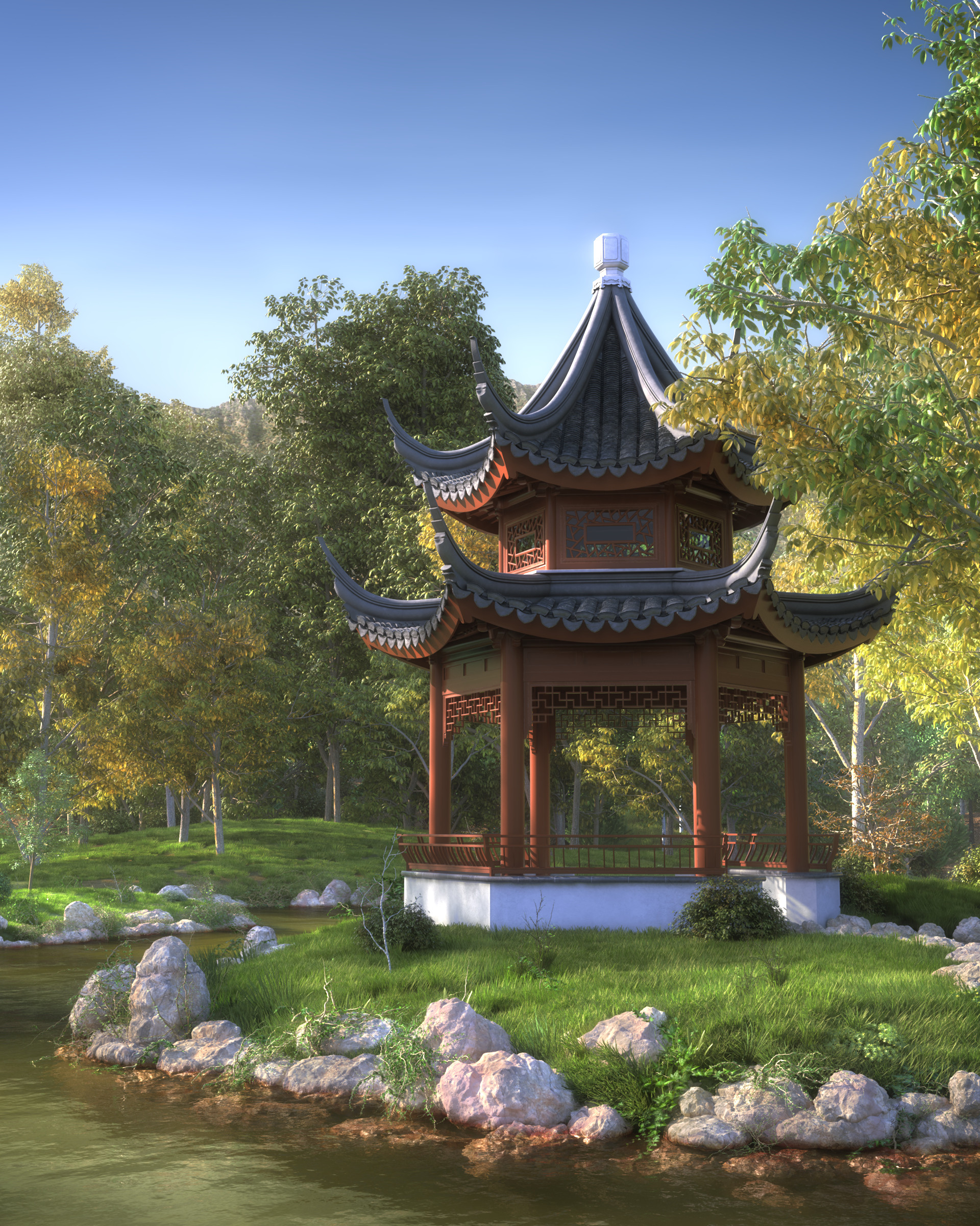
The Chinese Garden
the chinese garden
This project was inspired by the beautiful Huntington Botanical Garden’s Chinese Garden, located in San Marino, California. I wanted to start a personal project with artistic and technical challenges and this was the first major personal project I’ve had in the past 6 years. The project took a little bit more than a year to get finished and happened during a transition in my professional life when I left Blur Studio and started at Blizzard Entertainment, in the Cinematic Department.
Modeling
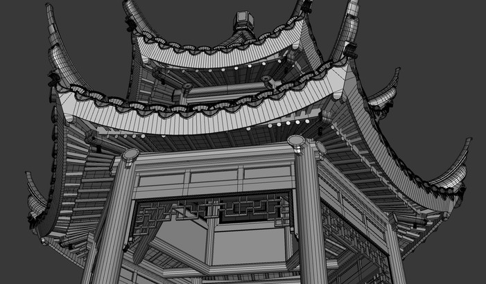
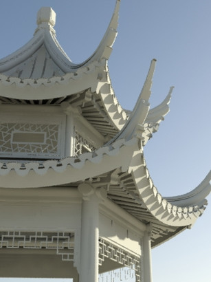
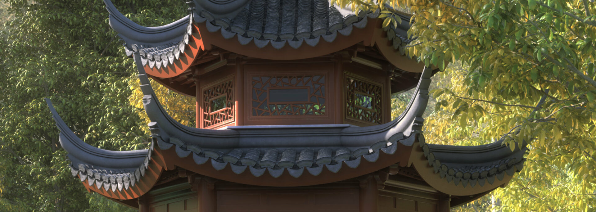
I started modeling the pavilion using some reference pictures from the web. I’ve tried to recreate the whole structure as close as possible to the real pavilion; parts not visible in the final picture were also modeled. Most of the external parts of the model were exactly the same in each of its 6 sides.
Roof Modeling
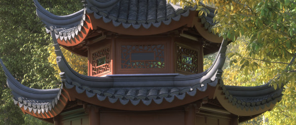
I wanted to have in my model the same curvature and number of tiles per row like in the real pavilion. Some rows had 78 tiles and it would be near to impossible to manually correct and readjust their position and overall curvature. The easiest way of doing that was having the basic curvature defined by splines and each tile path constrained to those splines. This way, I could move the splines’ knots and all the roof tiles would follow the same curvature. Using a small maxscript I could ensure that all roof tiles were always equidistant.
Materials and Shaders
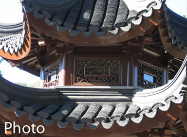
Whenever working with shader development, I like to think simultaneously about light intensity and camera response. I can’t start creating and tweaking shaders without knowing what is the camera response and what the CG light would be in our physical world. Shader details like reflection properties and color can’t be correctly adjusted if the exposure value and the physical light intensities are ignored. Due to the fact that each picture used as reference for modeling had a different color temperature because they were taken with different cameras under different light conditions, they were not reliable as references for the shader development.
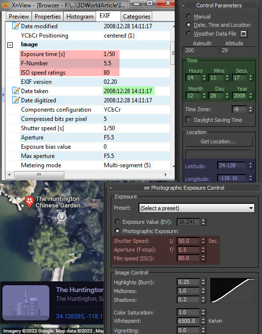
Because of that, I’ve decided to visit the Chinese Garden and take some pictures myself. These new reference photos contained also important information for my light and camera variables: I’ve got all exposure information from the pictures and used it as configuration for the Mental Ray exposure control. Also, I’ve got the exact time when the pictures were taken and elected one single picture to be my main reference. Then, I’ve used the GPS and time information and configured the Daylight System to properly represent the same lighting situation as it was in the moment my reference picture was taken. At this point, I was sure that the light and camera response were nailed down, so, if the shader resembles closely the material from the picture, I know this shader will be accurate under any lighting condition in my 3d scene.
Libraries
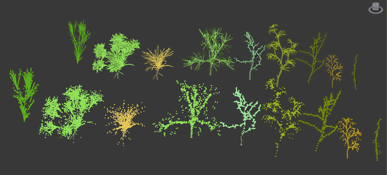
This project used Mental Ray Proxies extensively (in fact, the use of Mental Ray Proxies allowed the render of all scene objects in a single pass). Some libraries were created (rocks, grass, small vegetation, ivies and trees) and later laid out through the scene. MR proxies are useful for the memory management because the geometry doesn’t need to be loaded in 3ds max and is loaded only when needed by Mental Ray.
The small vegetation library was created with PlantStudio2 (http://www.kurtz-fernhout.com/PlantStudio/) and IvyGenerator (http://www.guruware.at/main/). After the creation, the libraries were converted to MR Proxies.
The rocks were created out of geodesical spheres procedurally modified by a combination of noise, smoke, cellular and splat displacement maps. The grass modeling process is really simple – a bunch of bent blades collapsed together.
Some problems came with the use of MR Proxies. Grass patches converted to MR Proxies cannot be scattered regularly neither used as particles. There was no easy way of planting the grass into the ground, so I needed to create a script that would duplicate the MR Proxy grass patches and position constraint them to the ground surface. This script would also be used for random transformations like offset translation, scale and rotation.
MR Proxies are represented by point clouds in the viewport and it’s impossible to find intersections between point clouds. This script was also used to switch back and forth between MR Proxies and their mesh counterparts. This way I could position objects visualizing them in the viewport and when the layout was good, switch them back to MR Proxies again.
Another important tool for this project was a script used to create branches and trees. This tool was not entirely developed and is not production proven, but it was fine for what I needed. The workflow for this tool will be covered in the next section.
Tools
Some problems came with the use of MR Proxies. Grass patches converted to MR Proxies cannot be scattered regularly neither used as particles. There was no easy way of planting the grass into the ground, so I needed to create a script that would duplicate the MR Proxy grass patches and position constraint them to the ground surface. This script would also be used for random transformations like offset translation, scale and rotation.
MR Proxies are represented by point clouds in the viewport and it’s impossible to find intersections between point clouds. This script was also used to switch back and forth between MR Proxies and their mesh counterparts. This way I could position objects visualizing them in the viewport and when the layout was good, switch them back to MR Proxies again.
Another important tool for this project was a script used to create branches and trees. This tool was not entirely developed and is not production proven, but it was fine for what I needed. The workflow for this tool will be covered in the next section.
Trees
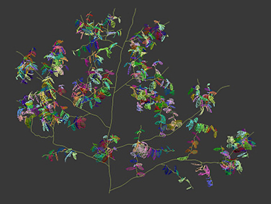
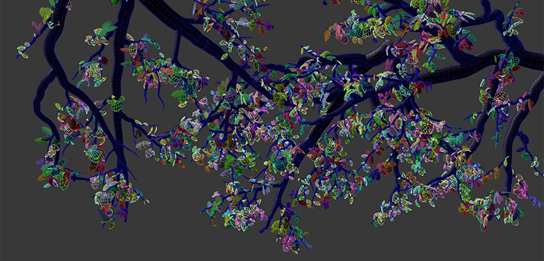
My initial idea was to spend most of the time working on the pavilion and find royalty-free 3D trees for the environment, but I couldn’t find trees with enough definition for the final 3000×4000 render – one of the most frequent problems was the disconnection between branches and leaves and that became too evident in the foreground trees. Because of that I decided to write a script to help in the creation of trees. The script works based on splines. The process consists in selecting a spline and creating branches. These new branches will be path connected to the selected spline. The second level of branches is created in the same way – the newly created branches are selected and new branches are created and connected to them. The reason why branches are connected to the parent spline is because if a parent branch (spline) has its knots edited and re-positioned, the child branches will follow the edit and will stay connected. The leaves creation utilizes the same principle. Any selected branch will receive leaves. Leaves have their pivot point on their bases and will be path connected to the branch splines. When the tree layout is defined, the splines are converted to geometry.
Water
Other than the regular shader components like reflection, refraction and bump maps, the water uses Parti Volume shader in the volume component. Parti Volume creates a nice murky look; light passes through the surface and scatters as it goes deeper. The Parti Volume shader requires a 3D object to work properly, so the water geometry is a box instead of a plane.
Compositing
This project was originally designed to be rendered in a single pass, but with the final image already rendered, I’ve decided to add more details, like displacements on the trees and roof tiles and a few more trees in the background. During the compositing stage, other than these details I also balanced isolated components such as diffuse color, reflections, ambient occlusions and overexposed areas and added some atmosphere passes.


